NEMA 17 Customization: Shaft, Connector, Gearbox, and Lead Screw
What OEM buyers should define early when requesting customized NEMA 17 assemblies for production programs.
Content Integrity Note
- Author: Jimmy Su
- Published: 2026/04/09
- Basis: Factory-side NEMA 17 OEM communication and validation workflows.
- Boundary: Final model and parameter decisions should be validated in your own system tests.
For OEM programs, the motor is only one part of the integration. Mechanical and harness details usually determine whether assembly can scale smoothly.
Customization Decision Flow (Before RFQ Freeze)
Shaft Customization
Typical options include:
- D-cut or round shaft
- Flat position and length tolerance
- Extended shaft or dual-shaft layout
- Surface finish or anti-corrosion treatment
Small shaft differences can break coupler fit and increase rework at your production line.
For production programs, define shaft tolerance expectation in RFQ. Otherwise, sample fit may pass while batch consistency becomes unstable.
Connector and Cable Definition
Define the harness standard early:
- Connector family and pinout
- Wire gauge and cable length
- Cable exit direction
- Labeling requirements for assembly line
If your plant has poka-yoke assembly rules, include keying and labeling constraints in the RFQ.
Also define whether cable strain relief and bend direction are fixed by your enclosure layout.
Harness Freeze Table (Recommended Before Pilot)
| Item | Example Spec | Inspection Method |
|---|---|---|
| Connector housing | JST/VH equivalent or buyer-defined | Visual + mating test |
| Pin assignment | Pin1-A+, Pin2-A-, Pin3-B+, Pin4-B- | Continuity and polarity check |
| Cable length | 300 mm +/- 10 mm | Tape measure check |
| Pull resistance | Buyer-defined minimum | Pull test sampling |
Gearbox and Lead Screw Integration
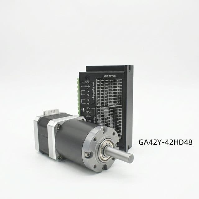
For motion modules, integrated assemblies reduce sourcing complexity:
- Planetary gearbox ratio options
- Backlash target and efficiency range
- Lead screw pitch and length
- Coupling and anti-backlash nut requirements
Request assembly-level tolerance targets, not only motor-level specs.
Gearbox/Lead Screw Validation Table
| Parameter | Typical Buyer Target | Risk if Missing |
|---|---|---|
| Gear ratio | Defined by cycle-time model | Wrong speed or torque balance |
| Backlash | Max limit by application | Positioning error in reversal |
| Screw pitch | Matched to required travel resolution | Inaccurate linear movement |
| Axial play | Controlled and documented | Repeatability drift |
Customization Impact Matrix (Planning Use)
| Custom Item | Typical Impact Area | Buyer Action |
|---|---|---|
| Shaft geometry change | Machining and fit validation | Provide mating component spec |
| Connector/pinout change | Harness BOM and assembly risk | Freeze pin definition before pilot |
| Gear ratio selection | Speed/torque envelope | Confirm real operating speed |
| Lead screw integration | Positioning and backlash behavior | Define travel and precision target |
This matrix helps sourcing teams separate “nice-to-have” from “must-freeze” items before placing mass-order PO.
Quality Control in OEM Projects
Ask suppliers to align on:
- Incoming material traceability
- Key dimensions and electrical checkpoints
- Sample approval criteria
- Change-control process for mass orders
This is essential for stable long-term procurement.
OEM Risk Register (Use in NPI Meetings)
| Risk | Early Signal | Preventive Action |
|---|---|---|
| Shaft-coupler mismatch | High rework in pilot build | Share mating part CAD and gauge data |
| Connector misbuild | Inverted phase wiring during assembly | Lock pinout drawing revision before PO |
| Gearbox backlash drift | Position error after burn-in | Add incoming and outgoing backlash checks |
| Uncontrolled engineering change | Batch difference vs approved sample | Formal ECN and dual-side sign-off process |
Buyer Checklist Before Sample Approval
- Mechanical fit confirmation in real assembly.
- Electrical compatibility with final driver settings.
- Thermal behavior under duty-cycle operation.
- Cable/connector usability in line-side installation.
- Documentation completeness (drawing, key specs, revision mark).
What to Send in Your First Inquiry
Share the following to speed up technical review:
- Application and installation constraints
- Electrical targets (current, voltage, torque, speed)
- Mechanical drawing or critical dimensions
- Quantity and shipment plan
Send to [email protected] to start OEM evaluation.
Related Tool
If the gearbox ratio is already being discussed, the 2:1 NEMA 17 gearbox calculator and sourcing report helps pre-screen output torque, speed loss, backlash risk, and whether adjacent 4:1 or 5:1 ratios should be quoted in parallel. For Duet-controlled printer builds using low-voltage windings, run the 2.9V NEMA 17 Duet setup checker and wiring report before freezing M906 current, connector pinout, and thermal validation notes.
For projects evaluating compact torque targets, the 0.25 N·m NEMA 17 fit checker and decision report helps you decide whether to keep direct drive or move to gearbox-assisted design before freezing customization details. For high-resolution motion plans, the 0.9 degree NEMA 17 pulse and resolution checker helps verify microstep and controller pulse margins before locking gearbox ratio and firmware settings.
Download Templates
Author

Jimmy Su
Export sales and application advisor for NEMA17Motor, focusing on OEM communication, technical alignment, and production handoff.
More Posts
NEMA 17 OEM RFQ Checklist for Global Buyers
A practical RFQ template to reduce back-and-forth and get faster, accurate quotations for NEMA 17 motor sourcing.
Open-Loop vs. Closed-Loop NEMA 17 Stepper Motors: 2026 Cost-Benefit Guide
A procurement and engineering guide comparing open-loop and closed-loop NEMA 17 stepper motors. Analyze costs, thermal efficiency, and when to upgrade.
How to Match NEMA 17 Torque, Current, and Driver Settings
A buyer-focused guide to avoid underpowered setups and overheating issues when selecting NEMA 17 motors and drivers.